A liquid-cooling manifold can pass a basic dimensional inspection and still be a poor part. A sealing face may move after machining. Welding can pull a port out of position. Heat tint or carbon-steel contamination can weaken the stainless surface. Chips left inside a passage can travel into a cold plate.
This is why stainless steel matters in AI server cooling. The grade on the material certificate is only the starting point. Reliability comes from the combination of grade, material condition, fabrication, surface treatment, cleanliness, and final inspection.
This article focuses on stainless distribution hardware: rack manifolds, piping assemblies, welded coolant components, brackets, and containment parts.
Liquid cooling changes what the rack has to support
High-density AI systems put the coolant loop inside the mechanical architecture of the rack. NVIDIA documents the GB200 NVL 72x1 as a single rack with 72 GPUs. Its Grace CPUs, Blackwell GPUs, ConnectX-7 devices, and NVLink switch ASICs are liquid cooled, while other components remain air cooled. That hybrid arrangement is a useful reminder: liquid cooling does not replace the rack. It adds fluid hardware to an already crowded structural, electrical, and service environment.
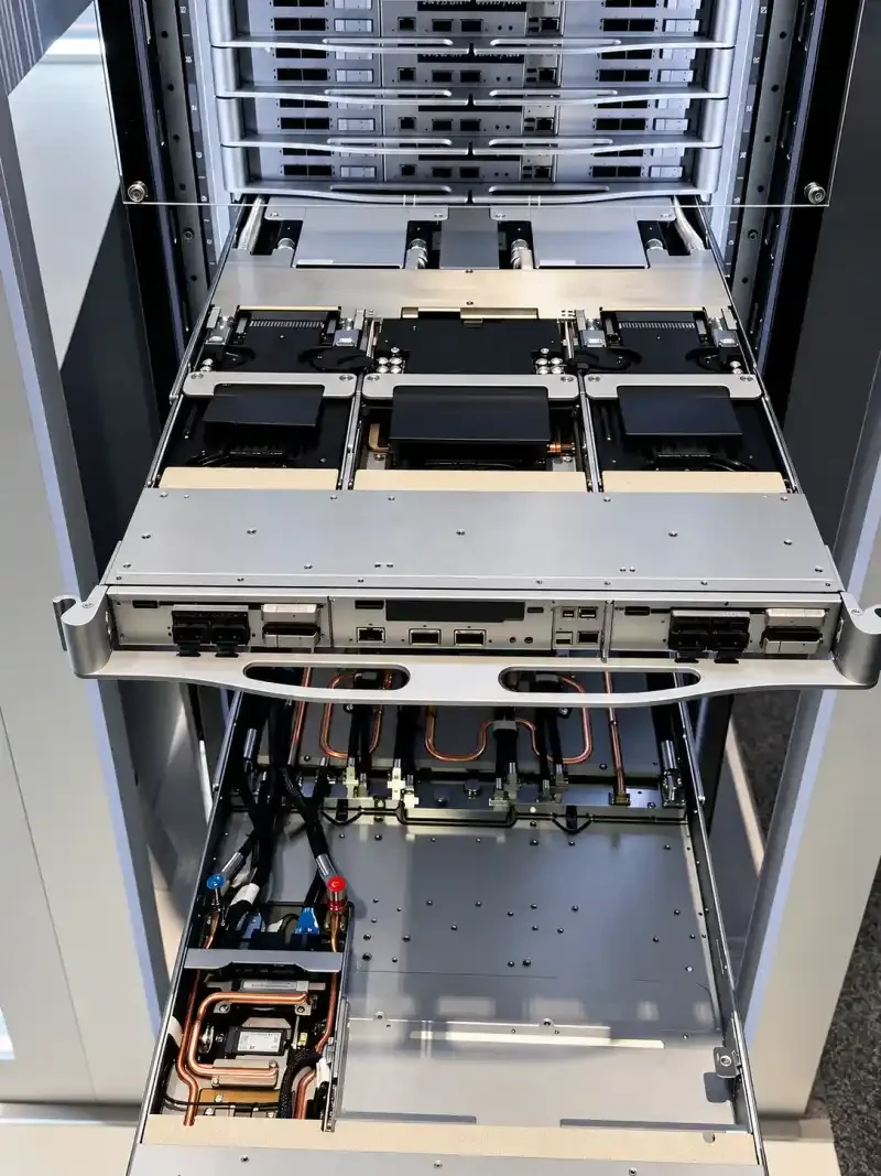
A typical direct-to-chip path may include a coolant distribution unit (CDU), supply and return manifolds, hoses, quick disconnects, and cold plates. The rack has to hold those parts in position without transferring unnecessary load into a fitting or sealing interface. It also needs room for hose bends, cable routing, valves, drip containment, and maintenance access.
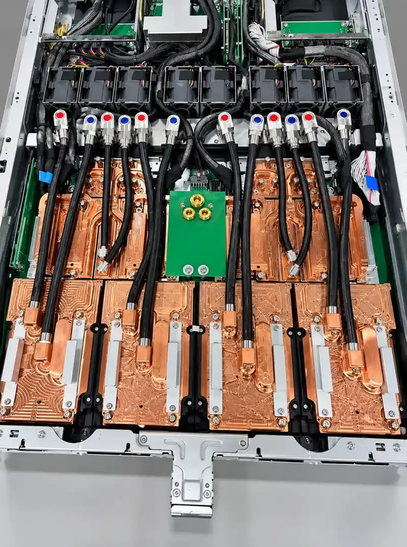
The manifold therefore has two jobs. Hydraulically, it distributes coolant. Mechanically, it must keep every connection where the mating hardware expects it to be. Material choice affects both jobs.
Where stainless steel fits—and where it does not
A liquid-cooling system is not made from one material. Copper is common in cold plates because it transfers heat well. Flexible polymers make hose routing possible. Aluminum may be useful in structural or thermal components when the complete wetted-material system supports it.
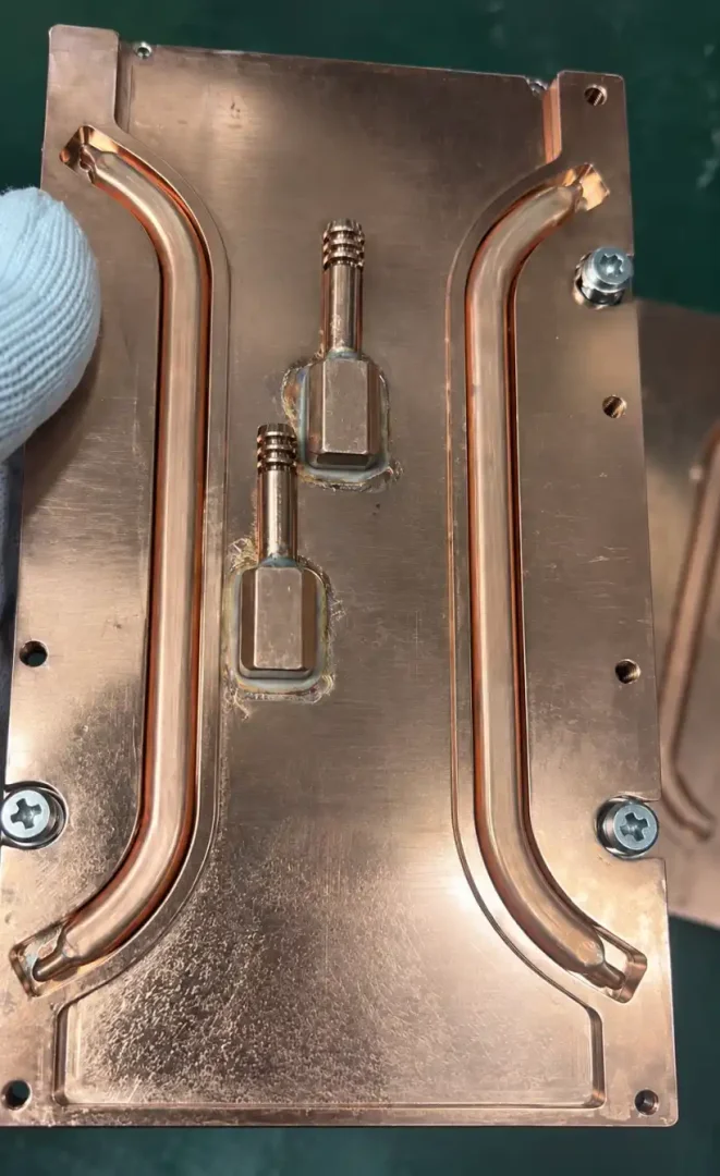
Stainless steel is most useful where corrosion resistance, weldability, structural strength, and clean fluid passages have to exist in the same part. Depending on the architecture, those parts may include:
- rack and row manifolds;
- coolant piping and welded distribution assemblies;
- machined ports, flanges, and valve bodies;
- manifold brackets and pipe supports;
- drip trays and leak-containment parts; and
- protective panels or frames around cooling hardware.
The Open Rack V3 blind-mate manifold specification lists 303, 304/304L, and 316/316L stainless steels among the permitted wetted materials for the manifold tube and end mounting brackets. That does not make every grade interchangeable. Coolant chemistry, temperature, pressure, joining method, surface finish, and the other materials in the loop still have to work together.
The first reliability problem is often contamination
Carbon steel remains a practical material for many rack frames and enclosures. The concern begins when an unsuitable carbon-steel surface is exposed to the coolant and corrosion products can enter the loop. Rust and oxide scale do more than make a part look poor. Loose material can move downstream toward small passages, seals, valves, or filters.
Manufacturing debris creates the same kind of system-level risk. A stainless component may have the right alloy and correct dimensions but still contain chips, burrs, grinding dust, oil, welding residue, or loose sealing material. For a conventional cabinet, that debris may be a workmanship defect. Inside a coolant path, it becomes a fluid-system defect.
Cutting, deburring, welding, cleaning, drying, inspection, and packaging should therefore be planned as one process. Compressed air alone is not a cleaning method. Open Compute Project guidance describes air drying as inadequate for removing foreign-object debris and calls for washing, followed by filtered air drying; it also recommends pressure or ultrasonic cleaning where the required cleanliness justifies it.
304L or 316L: start with the coolant, not the price list
304L and 316L are both austenitic stainless steels with good formability and weldability. The “L” denotes a low-carbon version, which reduces the risk of sensitization in welded areas and helps preserve corrosion resistance around the heat-affected zone.
The practical difference is molybdenum. 316L contains molybdenum, which gives it better resistance to localized attack such as pitting and crevice corrosion, particularly when chlorides are present. That added margin is useful, but it does not make 316L the automatic answer for every rack component.
| Engineering condition | 304L | 316L |
|---|---|---|
| Controlled closed loop with low chloride and validated chemistry | Often the practical cost/performance choice | Suitable, but the extra corrosion margin may not be necessary |
| Wetted manifold or piping with uncertain or more aggressive chemistry | Requires a project-specific compatibility check | Often the safer starting point |
| Condensation-prone or chloride-bearing environment | Use only when the exposure is understood and accepted | Better resistance to pitting and crevice corrosion |
| Non-wetted brackets, trays, frames, and enclosures | Commonly sufficient indoors | Useful when the surrounding environment demands more resistance |
| Weldability and formability | Very good | Very good |
| Relative material cost | Lower | Higher |
Choose the grade only after reviewing the complete fluid system. The OCP propylene-glycol guidance identifies 304L, 316L, or higher grades as preferred stainless options, while also requiring compatibility between the heat-transfer fluid and every wetted material, seal, connector, and operating condition.
A well-made 304L part can outperform a poorly fabricated 316L part. The alloy gives the part corrosion potential; the manufacturing route determines how much of that potential survives.
Material condition matters as much as the grade
“316L” describes chemistry. It does not describe how much residual stress the stock carries, how uniform its structure is, or how it will move when material is removed.
Material control starts before welding. Cut blanks and formed sections need to remain tied to the specified grade, heat number, and supply condition. Once mill markings are cut away, shop travelers or part-level identification have to carry that traceability forward.
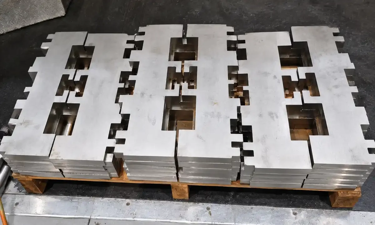
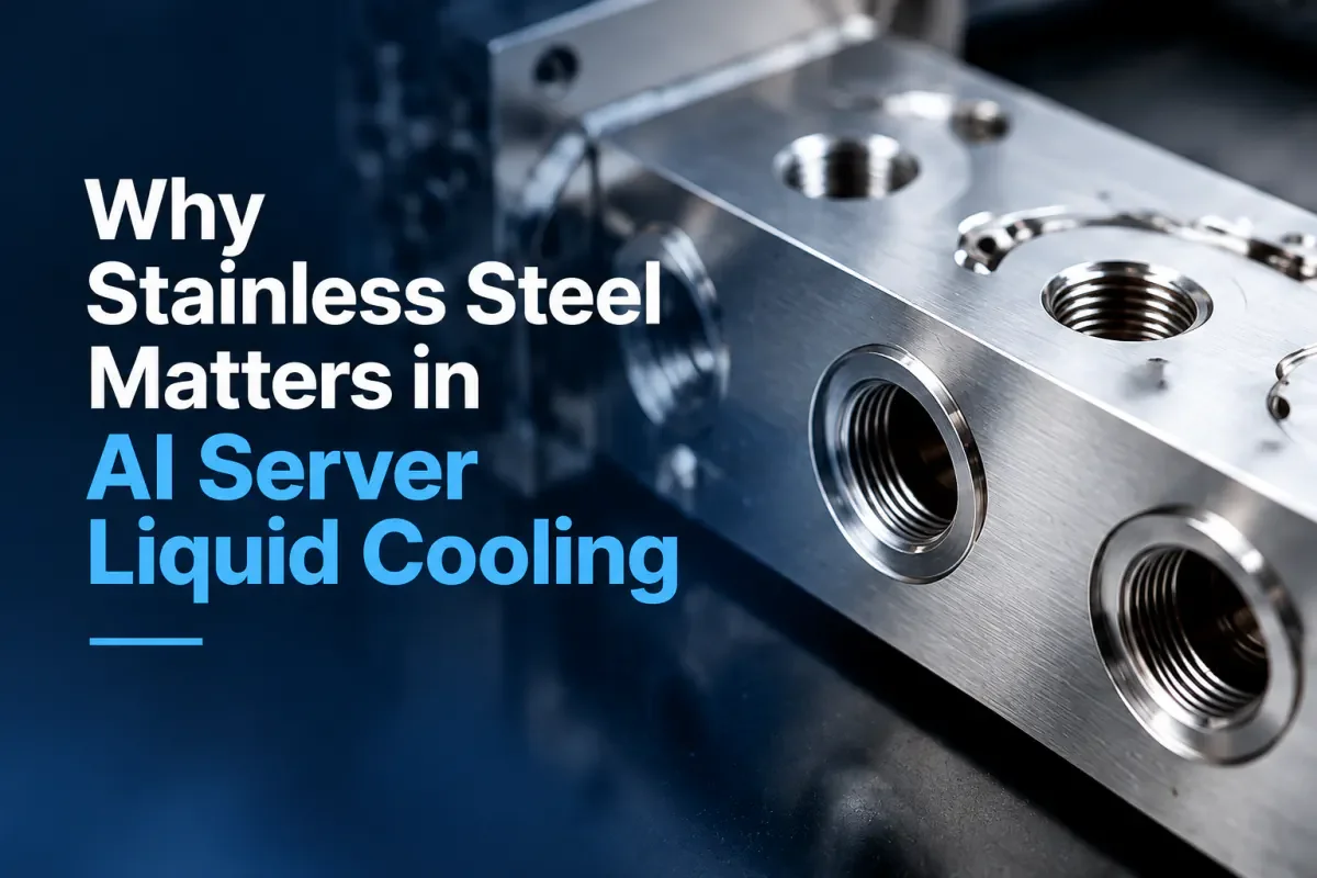
For the eccentric liquid-cooling manifold shown below, the starting stock is a rectangular 316L stainless section. That profile affects where ports, end closures, welds, and supports can be placed. Wall thickness, seam location, straightness, and machining allowance therefore belong in the drawing review before any port is cut.
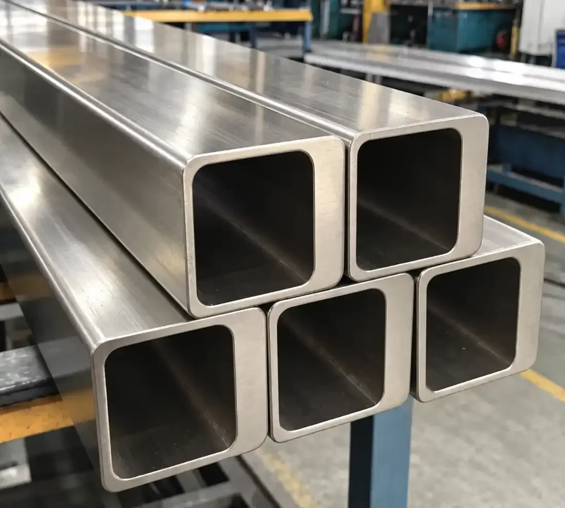
For higher-reliability liquid-cooling components, our material specification starts with mill-supplied solution-annealed stainless steel. When a project requires tighter control, ASTM grain size No. 6 or finer can also be specified with supporting mill documentation and lot traceability.
| Material condition | Manufacturing effect |
|---|---|
| Mill solution-annealed condition | Provides a more uniform austenitic starting structure after prior working |
| Controlled grain structure | Improves consistency between documented material lots |
| ASTM grain size No. 6 or finer, when specified | Creates a measurable material requirement rather than an informal visual judgment |
| Lower and more uniform residual stress | Reduces unpredictable movement during machining and welding |
| Mill documentation and heat traceability | Links the fabricated part to the specified grade and condition |
ASTM E112 explains how to measure and report average grain size. It does not set an acceptance limit for a manifold. If grain size No. 6 or finer is required, that limit must come from the project specification, and the inspection report should identify the method and material lot.
Solution annealing is also not a guarantee that a finished part will remain perfectly stable. Cutting, cold forming, welding, and uneven heat input can introduce new stress. The benefit is a more consistent starting point for the operations that follow.
Machining can release stress at a sealing face
Consider a welded or machined stainless component with a gasket face or O-ring seat. Removing material from one side changes the internal stress balance. A surface may be correct while it is clamped in the machine and move after it is released, after another feature is cut, or after welding.
For a structural bracket, a small movement may be absorbed during assembly. A sealing interface has less room for forgiveness. Flatness affects contact pressure. Port position affects connector alignment. A tilted or distorted face can load the seal unevenly even when every nominal dimension looks reasonable on the drawing.
The manufacturing sequence should therefore follow the functional surface. Rough machining, welding, stress stabilization where the process requires it, finish machining, and final inspection have to be ordered so that the sealing face is verified after the operations most likely to move it. Measuring too early only confirms an intermediate condition.
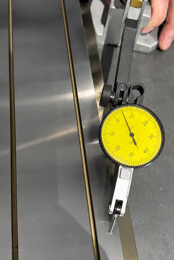
Surface finish matters with flatness. OCP’s rack-manifold qualification guidance identifies O-ring seats as a likely leakage point and gives Ra ≤ 63 µin (1.6 µm) as an example requirement, depending on seal type and size. That value should not be copied blindly onto every face; it is a useful reminder that geometry and texture must be specified together for the actual seal.
Welding can move a port even when the bead looks good
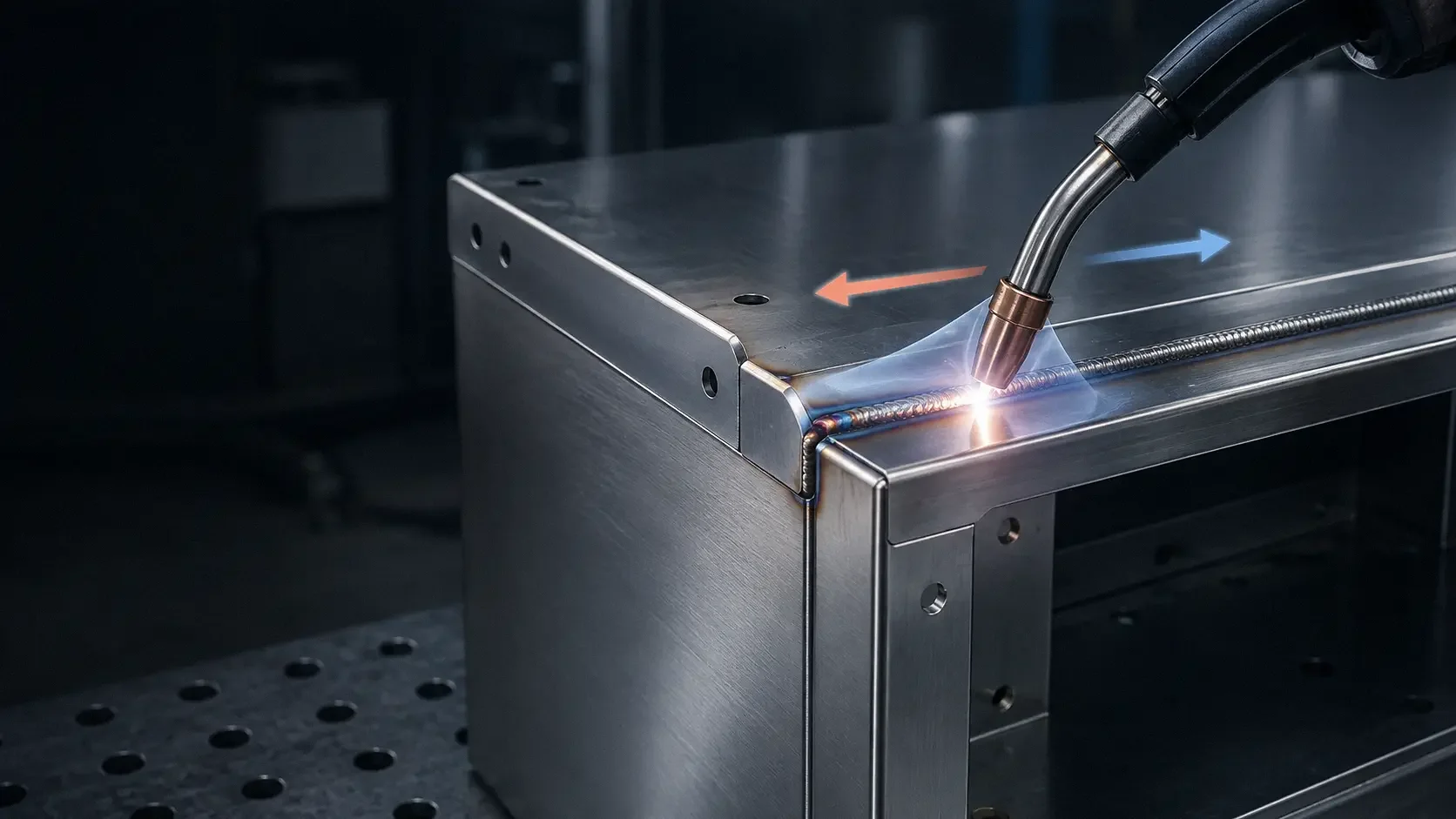
Stainless steel expands noticeably when heated. On a manifold with several ports, each weld shrinks as it cools. The movement from one joint may be small, but the sequence can accumulate enough error to shift a quick-disconnect centerline, twist a mounting foot, or pull a flange out of flatness.
Visual weld quality cannot answer those questions. A clean bead may still belong to an assembly that no longer fits.
The drawing and manufacturing plan need different information. The drawing defines the required port locations, datums, sealing faces, finished dimensions, and leak or pressure-test requirements. The welding procedure controls joint preparation, filler, shielding, heat input, sequence, and acceptance. Fixtures should restrain the assembly without hiding distortion that will appear as soon as the part is released.
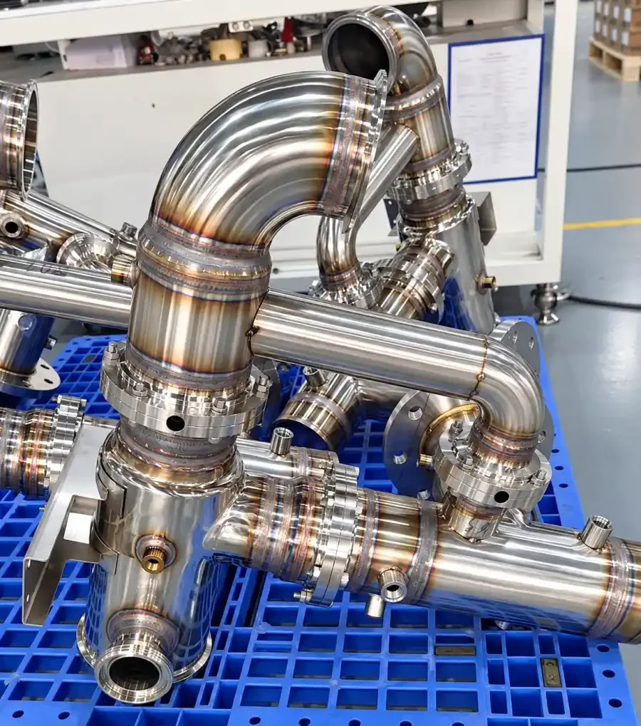
For stainless manifolds, OCP guidance recommends TIG welding in an inert-gas environment with filler compatible with the base material. It also calls for descaling and pickling/passivation after welding, plus deburring and finishing of ports. Those steps are connected: the weld creates both the joint and a surface condition that must be restored.
Heat tint and shop contamination can undo a good material choice
Stainless steel resists corrosion because a thin chromium-rich passive film forms at the surface. Welding heat can produce oxide scale and heat tint. Grinding with contaminated tools can embed carbon-steel particles. Shop dust, marking compounds, and poor handling can leave a correctly specified alloy with a compromised surface.
The response depends on the part. A dry interior bracket does not need the same treatment as a wetted manifold. For fluid-contact hardware, however, the process may include dedicated stainless tools, controlled weld cleaning, heat-tint removal, pickling, passivation, or electropolishing. The required treatment should be tied to the alloy, coolant, weld condition, and cleanliness target—not added as a generic cosmetic note.
Cross-contamination is easy to miss during fabrication. Certified 316L can still pick up embedded iron when it is processed with a shared wire brush, grinding belt, fixture, or work surface. The material certificate remains correct, but the finished surface has been compromised.
Aluminum and stainless steel must be judged as part of the loop
Aluminum is light and thermally conductive, so it remains useful in many server components. Inside a mixed-metal coolant loop, however, its suitability depends on the fluid chemistry and every other wetted material.
Cold plates commonly contain copper. If aluminum, copper, stainless steel, plated fittings, elastomers, and coolant additives share one loop, the fluid chemistry and inhibitors must protect the entire combination. Galvanic couples, coating wear, crevices, temperature, and conductivity can change the corrosion behavior. A material that performs well in air may behave differently when it becomes a wetted component.
For a manifold or distribution pipe, thermal conductivity is usually less important than corrosion resistance, clean weldable joints, pressure integrity, and stable interfaces. That balance often favors 304L or 316L stainless steel. It is still an engineering choice, not a blanket ban on aluminum.
What final inspection should prove
The inspection plan should follow the ways the part can fail in service. For stainless liquid-cooling hardware, that normally means checking more than overall size.
- Material identity and condition: Verify the grade, heat number, solution-annealed condition, and any specified grain-size record.
- Wetted-material compatibility: Confirm the coolant, metals, seals, lubricants, connectors, and operating temperature are approved as one system.
- Port and mounting geometry: Inspect critical locations from functional datums after welding and final machining.
- Sealing interfaces: Check flatness, surface finish, damage, burrs, and edge condition in the final manufacturing state.
- Welded joints: Apply the specified visual, dimensional, leak, pressure, or nondestructive examination requirements.
- Internal cleanliness: Confirm that chips, flux, scale, oil, loose particles, and cleaning residue have been removed; dry the part with clean filtered air and protect openings after inspection.
- Surface restoration: Verify the required post-weld cleaning, pickling, passivation, or electropolishing has been completed without damaging threads or sealing faces.
- Final packaging: Cap fluid ports and keep the cleaned internal passage sealed until installation.
This sequence catches a common mistake: inspecting the feature before the process is finished. Port position checked before welding, flatness checked before final machining, or cleanliness checked before rework does not describe the shipped part.
What matters in the finished part
Stainless steel earns its place in AI server liquid cooling because it can combine corrosion resistance, weldability, structural strength, and clean fluid passages in one fabricated component. None of those advantages operates alone.
Use 304L when the verified coolant chemistry and exposure allow it. Move to 316L when chloride, condensation, crevice conditions, or uncertainty justify the additional pitting resistance. Then control the material condition, machining sequence, welding distortion, post-weld surface, internal cleanliness, and final inspection with the same care used to choose the grade.
A finished manifold has to remain clean, aligned, sealable, and corrosion resistant after every manufacturing operation is complete. The word “stainless” on the drawing cannot prove that by itself.